Gutter System PVC
Features
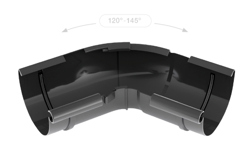
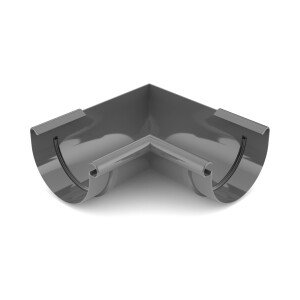
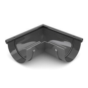
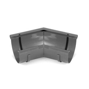
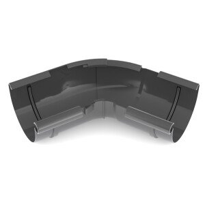
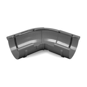
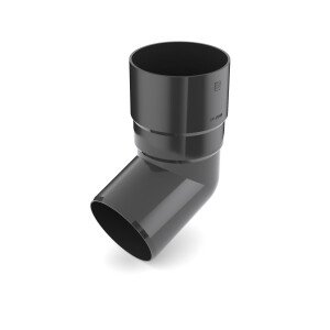
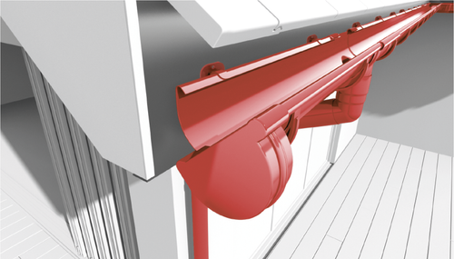
CORNERS OF ANGLE ADJUSTABLE IN THE 120°–145° RANGE
INNOVATION // COMFORT
An innovative product simplifying the assembly of gutter systems on non-standard roofs. It facilitates the assembly process, does not require gluing, eliminates the need for welding the corners.
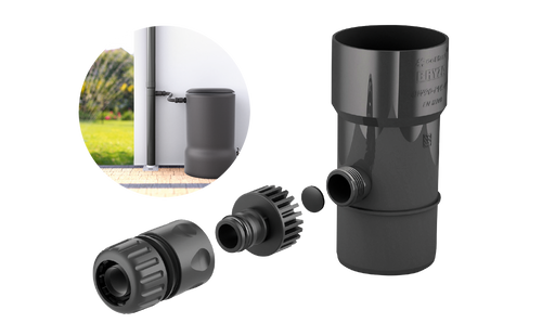
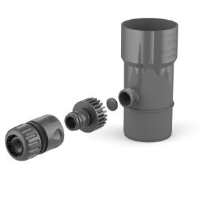
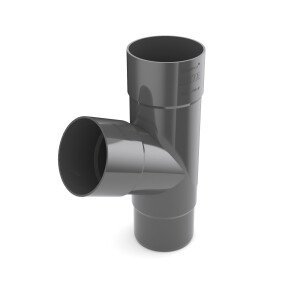
RAINWATER RECLAIMER
ECOLOGY // ECONOMY
Suitable for downpipes with diameters of 63,90 and 110 mm - the most popular sizes used in the construction industry. Offered in a set with a connection and quick connector in graphite colour, allowing to connect a garden hose and drain rainwater to a tank. An additional plug makes it possible to shut off the reclaimer outflow if necessary.
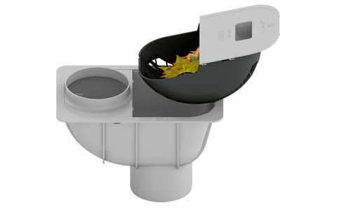
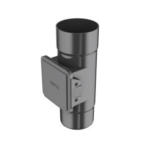
SEDIMENT TRAP
EFFICIENCY // ERGONOMICS
This element connects the gutter system with a storm water sewage system of 110 mm diameter. As a standard, it is adjusted to 110 mm diameter down pipes, however, it can also support such diameters as 100, 90 and 63 mm, provided a correct adapter is used. Available in four colour versions: brown, graphite, grey and black. Its main function is to retain impurities flowing from roof and prevent their discharge to storm water sewage system. It is equipped with a large retaining basket connected with a tilting flap, which facilitates removal of impurities.
System elements
System
Colors


assembly instructions
1GUTTER SYSTEM BRYZA PVC INSTALLATION
CORRECT INSTALLATION A GUARANTEE OF RELIABILITY
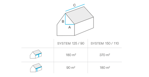
When choosing a gutter system, calculate the so-called Effective Roof Surface using the following formula: ERS = (A+B/2) x C A - horizontal distance from the corner to the roof ridge (m) B - roof height (m) C - roof length (m) 0°C Minimum installation temperature
2GENERAL ASSEMBLY RULES
Correct installation of a PVC gutter system is a guarantee of its long-term durability and reliability, even in difficult weather conditions. In comparison with traditional solutions, the main advantage of the construction is the ability to compensate for thermal changes in the length of its individual elements. This is achieved thanks to the appropriate design of gutter and pipe joints. In gutters, it is implemented through a slidable connection with gutter joints equipped with flexible gaskets, and in downpipes, through assembly slack at the connections with pipe joints. Moreover, elements that fasten the gutter system to the roof and building walls, such as gutter hangers and down pipe clamping rings, not only stabilize the system but also allow compensation for variations in its length. If gutters are fitted to gutter strips made of galvanised metal sheet, they must be painted or coated. The gutters under the eaves should be installed below the line which is an extension of the roof surface, so that they are not subjected to sliding snow loads.
3CORRECT LOCATION OF GUTTERS UNDER EAVES
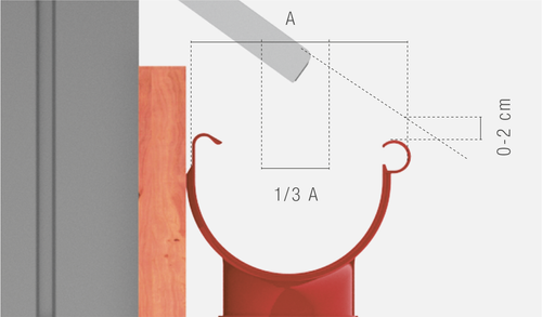
Correct installation must protect gutters against the impact of snow sliding down a roof. The upper edge of gutter flanging should not protrude over the extension of the roof surface, which is represented in the picture.
4CUTTING GUTTERS AND DOWN PIPES
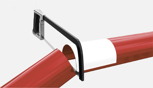
Cut the gutter into suitable length, at the right angle, with a fine-toothed saw.
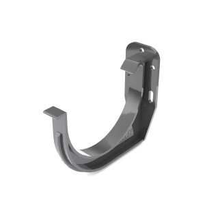
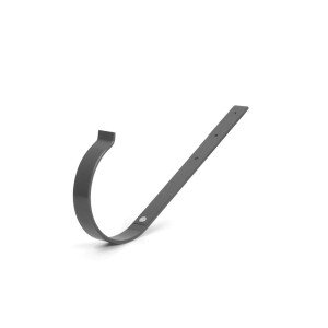
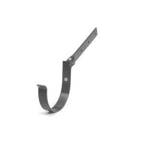
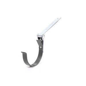
5INSTALLATION OF HANGERS
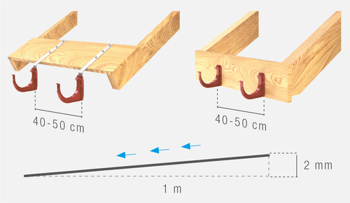
PVC hangers with straight or twisted fascia boards, as well as straight or twisted steel hangers are mounted directly to the laths or rafters. The distance between the hangers should be 40–50 cm. In order to drain water properly, gutters should have a decline in the direction of the drop outlet of min. 2 mm per 1 m.
6INSTALLATION OF HOOKS AND CLAMPING RINGS
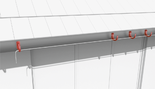
The first step in the system installation process is to locate an outlet drop, i.e. the lowest element of the system roof section.
7DETERMINING OF GUTTER DECLINE
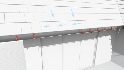
At first, mount the hanger located farthest from the drop outlet, and then the hanger next to the drop outlet. Extend two strings between the hangers and establish the correct decline of the gutter. PVC hangers are mounted directly to the face board.
8INSTALLATION OF GUTTERS IN HANGERS
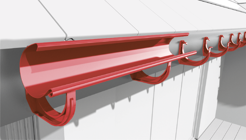
In PVC and metal hangers, the installation process should begin with putting the pipe flanging into the front nose of the hanger and then forcing in the internal part of the gutter under the rear nose.
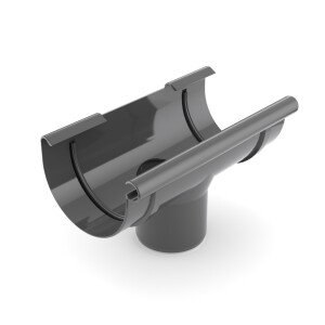
9INSTALLATION OF DROP OUTLET
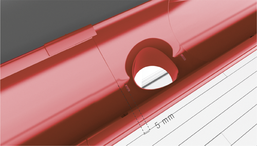
A corner, drop outlet and gutter joint should be mounted together by inserting onto the front gutter flanging and latching on the rear gutter flanging. Gutter ends should be situated around 5 mm in front of the limiters.
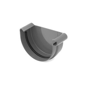
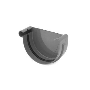
10INSTALLATION OF END CAP
Installation of the end cap should start from inserting it into the front gutter flanging and latching it on the rear gutter flanging. Pay attention to the correct position of the gaskets.
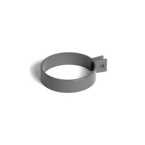
11INSTALLATION OF CLAMPING RINGS
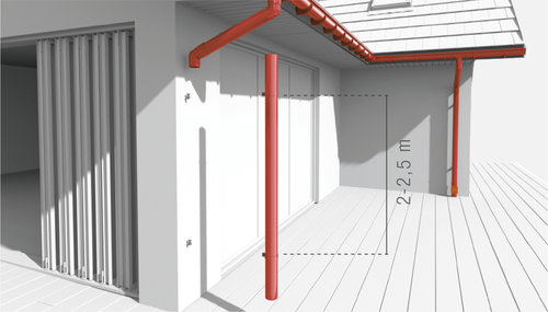
Clamping rings are fixed to a wall using clamp hooks of correct length. If necessary, an additional supporting façade flange is used. Clamping rings on down pipes should be spaced at least every 2–2.5 m.
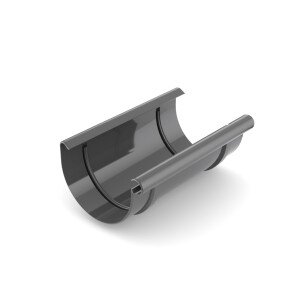
12INSTALLATION OF GUTTER JOINT
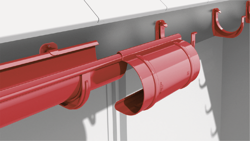
A corner, drop outlet and gutter joint should be mounted together by inserting onto the front gutter flanging and latching on the rear gutter flanging. Gutter ends should be situated around 5 mm in front of the limiters. While connecting, pay attention to a correct position of gaskets located in drop outlets, joints and corners, as well as to the limiters located on internal surfaces of these elements. We also recommend mounting additional gutter hangers on the gutter-gutter joint and gutter-drop outlet connections.
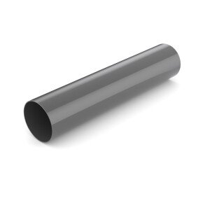
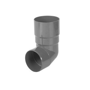
13INSTALLATION OF DOWN PIPES
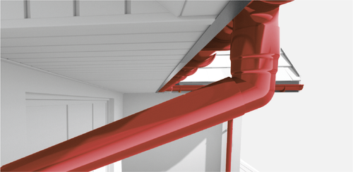
Connect down pipes with drop outlets, elbows and gutter joints using the push-fit system. In case the eaves protrude over 10 cm beyond the wall, the set-off should be extended by a section of a down pipe. Mount the elements in the following order: pipe elbow, pipe, pipe elbow and down pipe. Leave a 10 mm clearance to compensate for thermal expansion of the pipe.
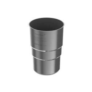
14INSTALLATION OF DOWN PIPE JOINTS
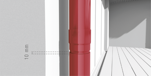
Connect down pipes using the push-fit system. Leave a 10 mm clearance in a joint socket to compensate for thermal expansion of the pipe.
15RAINWATER RECLAIMER
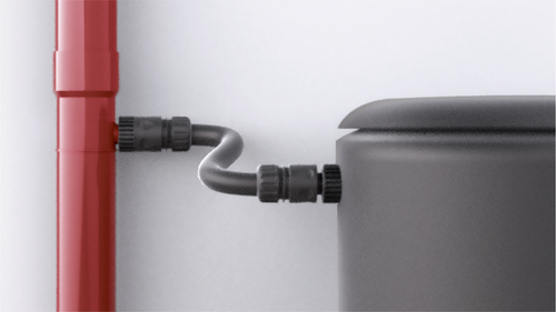
We recommend that a reclaimer should be installed in locations not subjected to serious pollution (e.g. tree leaves). In case the reclaimer cleaning is necessary, it should be flushed several times with pressurised water.
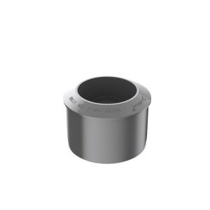
16INSTALLATION OF CLEAN-OUT
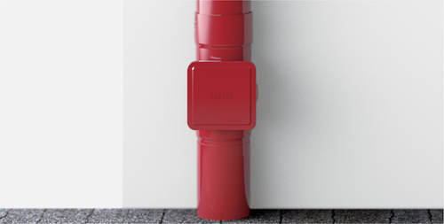
A clean-out should be mounted on the lower down pipe section when a gutter system is to be connected to a sewer system. Each clean-out comes with a strainer collecting impurities from a gutter. The whole is closed with a tight lid. The passage between a 110 mm diameter clean-out and a 90 mm diameter pipe may be connected using a reduction adapter.
17INSTALLATION OF SEDIMENT TRAP
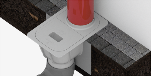
A sediment trap should be installed in the ground. It must be flushed with the final soil layer. In order to provide the necessary stability, pour concrete on an excavation bottom and connect the sewage system piping. After the final soil level is established, pour another layer of concrete around the sediment trap. Next, connect a down pipe.