Gutter System STAL
Specification
Features
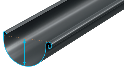
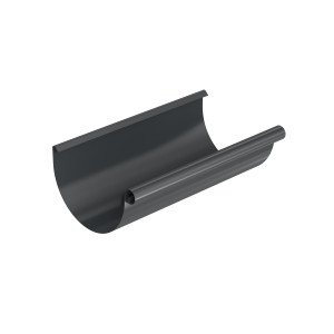
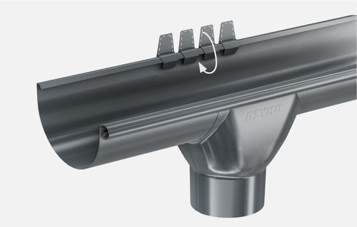
DEEP GUTTER
Deep gutter ensures proper rainwater drainage, even during heavy rainfall. System 125 - depth of 80 mm System 150 - depth of 92 mm
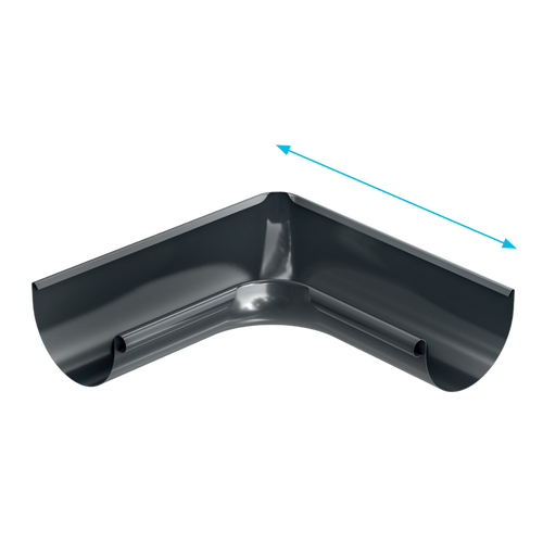
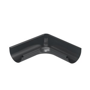
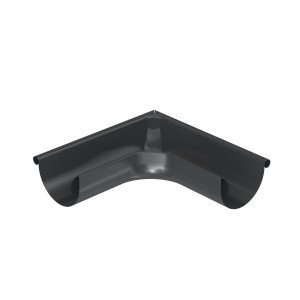
LONG CORNERS
Long arms of a corner provide the possibility of attaching a gutter hanger which stabilizes the corner when connected with a gutter joint.
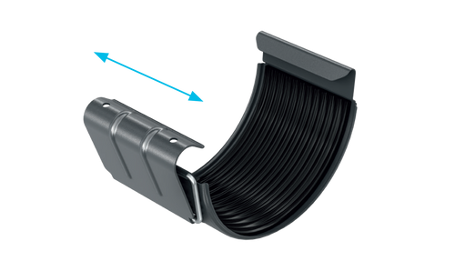
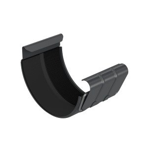
WIDE GUTTER JOINT
An 84 mm wide gutter joint with a rubber gasket ensures a stable and tight connection. Clamp fastening makes installation quick and easy.
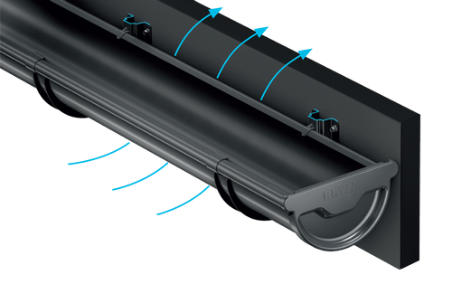
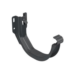
EASY VENTILATION
A specially designed deep-drawn gutter hanger moves the gutter away from the fascia board, providing more efficient ventilation of the roof slope.
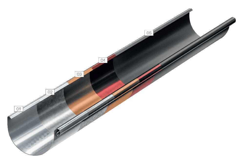
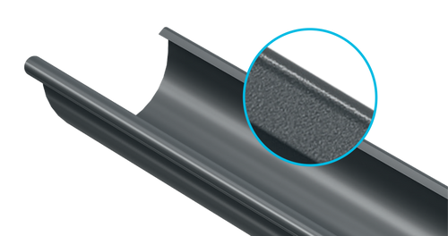
ENRICHED COATING
Multi-layer protection of the steel core and the polyurethane coating additionally protect against scratching and loss of colour.
System scheme
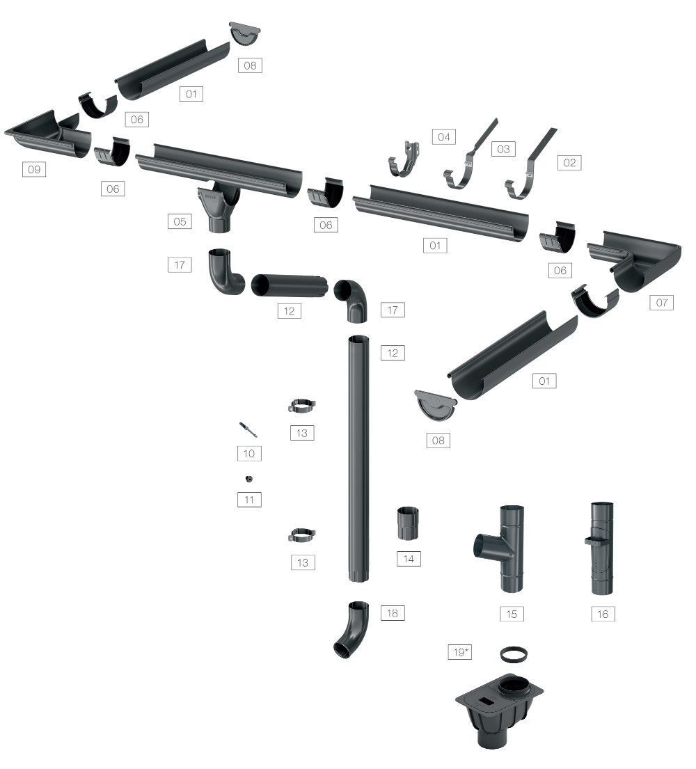
System elements
System
Colors


assembly instructions
1GUTTER SYSTEM BRYZA STAL INSTALLATION
CORRECT INSTALLATION A GUARANTEE OF RELIABILITY
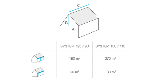
When choosing a gutter system, calculate the so-called Effective Roof Surface using the following formula: ERS = (A+B/2) x C A - horizontal distance from the corner to the roof ridge (m) B - roof heigh [m] C - roof length [m]
2LOCATION OF GUTTER UNDER EAVES
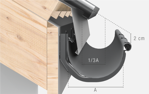
Correct installation must protect gutters against the impact of snow sliding down a roof. The upper edge of gutter flanging should be lowered below the extension of the roof slope surface.
3GUTTER DECLINE
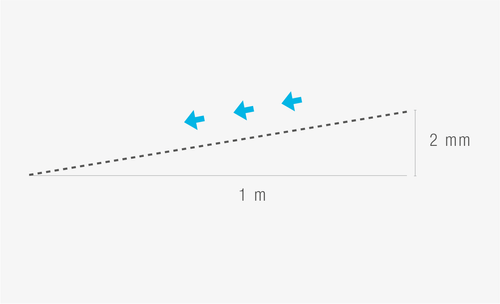
Extend a string between the highest and the lowest hanger. This helps determine the position of the rest of the hangers. The decline of the gutter towards the drain should be at least 2 mm per 1 m.
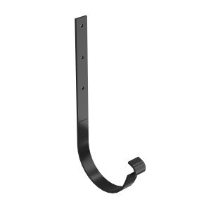
4GUTTER HANGERS
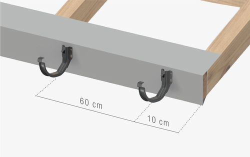
Gutter hangers should be mounted directly to the face board at 60 cm intervals. The first hanger should be placed 10 cm away from the roof edge.
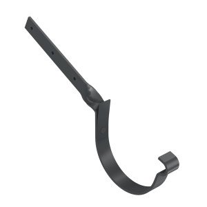
5RAFTER HOOKS
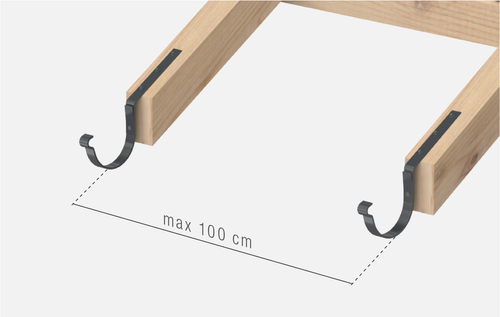
Rafter hooks should be installed at the maximum spacing of 1 m. The hooks should be distanced from the rafter edge at least 2 cm to allow free ventilation of the roof (Fig. 1.4.).
6SPACING OF HOOKS
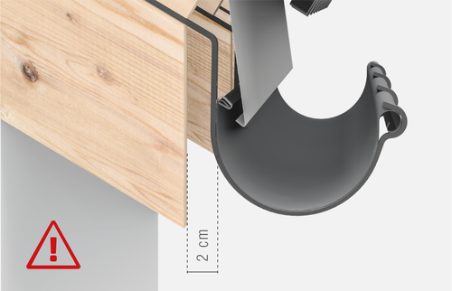
The distance between the rafter hooks and the edge of rafters should be 2 cm, which allows for free ventilation of the roof, especially in difficult winter conditions. Lack of appropriate spacing prevents correct installation of corners.
7INSTALLATION OF DOWN PIPE AND DROP OUTLET
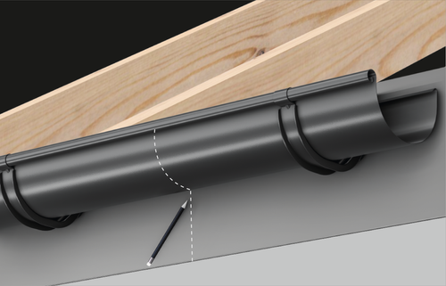
After installing the hangers, place the gutter in them and mark the position of the drop outlet at the lowest point.
8LOCATION OF DROP OUTLET
Use a soft pencil to outline the edge of the drop outlet on the surface of the gutter.
9CUTTING OUT THE DRAIN HOLE
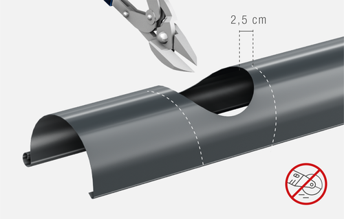
The drain hole must be cut out by using scissors. The use of high-speed tools is not permitted! The diameter of the hole should be reduced by approximately 2,5 cm in relation to the previously marked edge of the drop outlet.
10EDGE PROCESSING
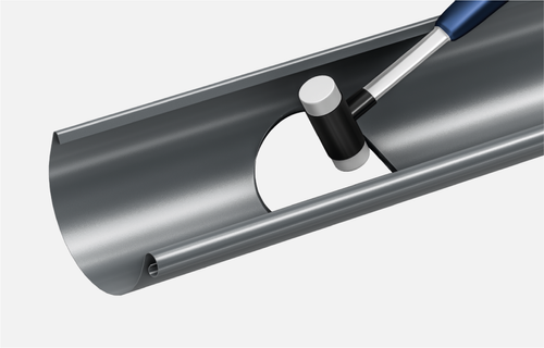
Profile the cut edge on the inside of the gutter using suitable tools that do not damage the gutter coating, e.g. a soft faced hammer.
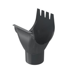
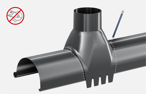
11INSTALLATION OF DROP OUTLET
Stability of the drop outlet is ensured by four mounting elements, the so-called leaves, which must be bent deep into the gutter flanging.
12GUTTER JOINTS
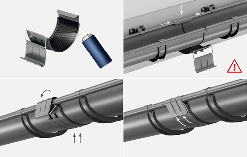
After latching the gutter joint on the rear flanging of the connected elemets, the joint with a gasket must be tightened and pressed from underneath. Only after pressing can the clamp be latched onto the front flanging and locked in place by bending the leaves.
13CORNERS
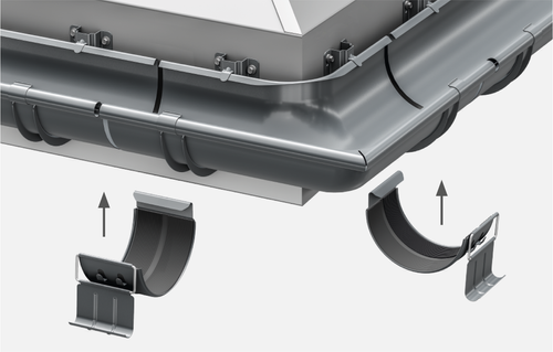
Connect corners to the gutters with gutter joints. It is necessary to use additional gutter hangers to stabilise the system. In order to ensure proper dilatation of the system, leave a 5 mm gap at the connection between the corner and the gutter. Mount the additional gutter hangers maximum 15 cm from the centre of the gutter joint.
14INSTALLATION OF GUTTER HANGERS AND CLUMPS
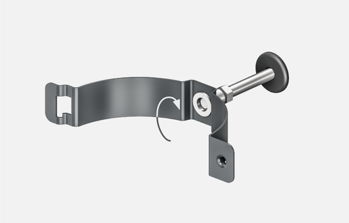
The first step is to drill a hole in the wall. We recommend using a stabilising flange. Screw the back part of the clamping ring with an appropriate thread onto the screwed hook.
15VERTICALISATION OF DOWN PIPE
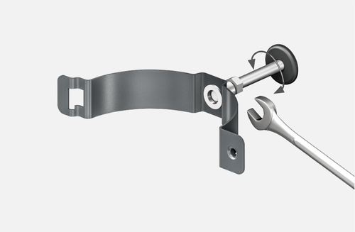
Always use a spanner for screwing in or unscrewing the clamping ring when verticalisation of the down pipe.
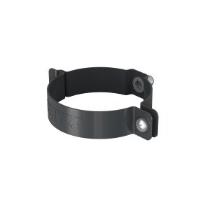
16INSTALLATION OF DOWN PIPE CLAMPING RINGS
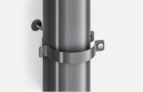
After screwing on the back part of the clamping ring, push the front part into the socket and screwed tight. Down pipe clamping rings should be installed at least every 2 m.
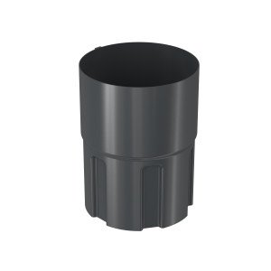
17CONNECTION OF DOWN PIPES
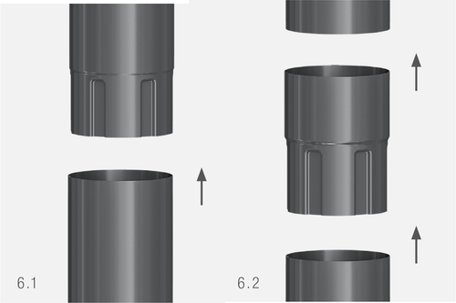
Down pipes have a socket end (fig. 6.1). In case of a pipe with a cut off end, use a pipe joint (Fig. 6.2).
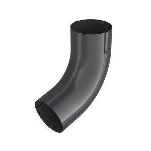
18INSTALLATION OF DOWNSPOUT SHOE
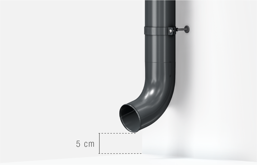
The downspout shoe should be installed min. 5 cm above the ground surface. There can also be used a sediment trap from the BRYZA PVC gutter system.
19INSTALLATION OF PVC SEDIMENT TRAP
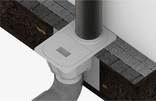
Install the sediment trap in the ground, making sure to flush it with the final ground surface. In order to provide the necessary stability, pour concrete on an excavation bottom and connect the sewage system piping. After establishing the final ground level, pour another layer of concrete around the sediment trap. Then connect the down pipe.